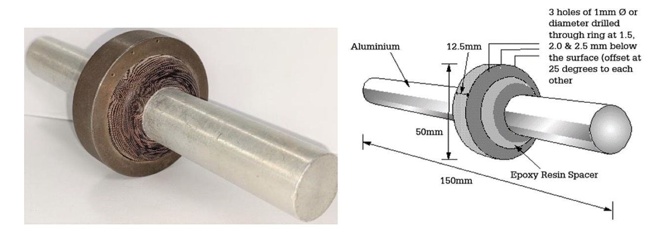
Current Flow (Headshots) – Test Piece 1 (TP1)
When current flow techniques are used on bench units, the following test should be carried out for each wave form available for use:
- Ensure the test piece is thoroughly demagnetised and pre-cleaned satisfactorily.
- Position the test piece (see diagram below) between the head and tailstock of the bench equipment.
- Slowly introduce a current and apply ink until the first hole (closest to the external surface) is visible.
- Note the applied amperage and continue to apply the current progressively until the second and third holes are noted.
Magnetic flow - Using Test Piece 4 (TP4)
If magnetic flow is being used, a similar procedure to the above would still apply, except that the dial readings/switch settings would be taken instead of amperage values and the following test piece would be used.
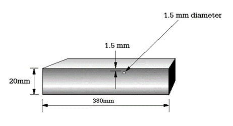
Fig. 8.6 - Test piece for magnetic flow and rigid coil techniques
A similar version is often used but with 5 holes (1 to 5mm) depths from the top surface) to assess the equipment over a greater range.
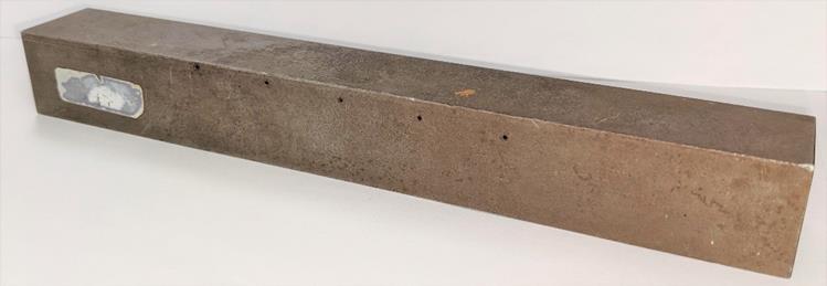
Rigid coil
If a rigid coil is being used the magnetic flow reference block would be employed, being placed within the coil and again noting amperages when the hole(s) become visible.